No edit summary Tag: sourceedit |
(full size pinout/moved up) Tag: rte-source |
||
| (18 intermediate revisions by 2 users not shown) | |||
| Line 1: | Line 1: | ||
| − | What is an Ostrich 2.0? Without getting too technical, it is a flashable EEPROM chip that acts as a "buffer" between your laptop and the ECU and makes tuning modifications possible without having to flash the stock EEPROM chip every time, saving much time! This is how to install an Ostrich 2. |
+ | What is an Ostrich 2.0? Without getting too technical, it is a flashable EEPROM chip that acts as a "buffer" between your laptop and the ECU and makes tuning modifications possible without having to flash the stock EEPROM chip every time, saving much time! This is how to install an Ostrich 2.0 module. |
| + | [http://volvospeed.com/vs_forum/topic/159506-tuners-rejoice-free-tuning-for-m44/page-74#entry2290850 Refer to Post#1480 Jan14 2013 by Simply Volvo] |
||
| − | This is the ostrich pinout |
||
| − | <center>[[File:Pinout.png|thumb|425x425px]]</center> |
||
| ⚫ | |||
| − | + | Components you need: |
|
| − | # http://www.moates.ne...EPROM Emulator. |
||
| − | # http://www.ebay.com/...in Floppy Cable |
||
| − | # An Ecu |
||
| + | [[File:Gallery_44472_1215_96313.jpg|none]] |
||
| ⚫ | |||
| + | [https://www.moates.net/ostrich-20-the-new-breed-p-169.html Ostrich 2.0 Module] |
||
| ⚫ | |||
| + | Floppy Cable such as [http://www.ebay.com/itm/24-inch-34-Pin-IDC-Floppy-Drive-Ribbon-Extension-Cable-Cord-CablesOnline-FF-004-/270837785829?pt=US_Drive_Cables_dapters&hash=item3f0f30a4e5%2032%20Pin%20Floppy%20Cable this] |
||
| ⚫ | |||
| + | Your ECU |
||
| ⚫ | |||
| ⚫ | |||
| ⚫ | |||
| + | First things first, you're going to open up the ECU: |
||
| ⚫ | |||
| + | [[File:Gallery_44472_1215_14786.jpg|none]] |
||
| ⚫ | |||
| + | [[File:Gallery_44472_1215_9369.jpg|none]] |
||
| + | All opened up: |
||
| + | [[File:Gallery_44472_1215_166121.jpg|none]] |
||
| + | Here is the stock EEPROM Chip (right under the toggle): |
||
| − | Alright, here are some pictures of me splitting cables: |
||
| + | [[File:Gallery_44472_1215_112913.jpg|none]] |
||
| + | Next you'll want to remove the chip, Simply Volvo used a dremel but here is an alternate recommended method: |
||
| + | [[File:Removing a Soldered PLCC EEPROM without expensive tools|center|601 px]] |
||
| + | It should look like this once the chip is removed and all cleaned up: |
||
| ⚫ | |||
| + | [[File:Gallery_44472_1215_106961.jpg|none]] |
||
| + | Now for the actual install, you have a couple of options to get it all wired up: |
||
| + | '''Method 1 (soldering floppy cable to the ECU)''' |
||
| + | '''First, here is a pinout of the EEPROM chip pinout:''' |
||
| − | Cables Split |
||
| + | [[File:Gallery_44472_1215_5255.png|link=http://m44.wikia.com/wiki/File:Gallery_44472_1215_5255.png|left]] |
||
| ⚫ | |||
| + | [[File:Pinout.png|none]] |
||
| + | |||
| ⚫ | |||
| + | |||
| ⚫ | |||
| + | |||
| ⚫ | |||
| + | |||
| ⚫ | |||
| + | |||
| ⚫ | |||
| + | |||
| ⚫ | |||
| − | Cables Split and the ones that do not have anything disconnected, cut |
||
| + | [[File:Gallery_44472_1215_2490.jpg|none]] |
||
| ⚫ | |||
| + | [[File:Gallery_44472_1215_84706.jpg|none]] |
||
| − | Taking apart ECU |
||
| ⚫ | pin 1 is the wire that is pink (or colored). So the pink wire would correlate upper most right on the ostrich connector, but since nothing is connected to that I just snipped it. Pin 2, bottom most right is the second wire on the ribbon cable (next to the pink). That has no connection either so can be cut. The next wire correlates to pin 3, which is VCCT. You can now follow the pattern below to figure out which wires correlate to which pin. |
||
| + | [[File:Screen Shot 2015-02-20 at 8.06.40 PM.png|none]] |
||
| + | Split the cables: |
||
| + | [[File:Gallery_44472_1215_65009.jpg|none]] |
||
| + | You can go ahead and cut away the wires you don't need: |
||
| + | [[File:Gallery_44472_1215_70979.jpg|none]] |
||
| − | There is the flash chip |
||
| ⚫ | |||
| + | [[File:Gallery_44472_1215_115984.jpg|none]] |
||
| + | All buttoned up again: |
||
| + | [[File:Gallery_44472_1215_1292.jpg|none]] |
||
| ⚫ | |||
| − | In order to get the flash chip off, I used a dremel. If i were to do it again, I would do this method: |
||
| ⚫ | |||
| + | For the alternate method, you will ''also ''need: |
||
| + | [http://www.mouser.com/ProductDetail/3M-Electronic-Solutions-Division/8432-21B1-RK-TP/?qs=sGAEpiMZZMs%2FSh%2Fkjph1tvt1%2FmEPT%2FXop1%252bdlxwofrg%3D PLCC32 Socket] |
||
| + | DIP-32 to PLCC-32 IC Adapter[http://www.epboard.com/eproducts/protoadapter2.htm (Part E32-0035)] |
||
| − | All finished |
||
| + | [https://www.moates.net/emuc3206-emulation-cable-32pin-6inch-p-168.html?cPath=32 32 Pin Ostrich Cable] |
||
| ⚫ | |||
| ⚫ | |||
| − | For those of you like Hussein who do not want to solder here is method 2. |
||
| + | [[File:Null_zpsd6fc9aff.jpg|thumb|none|640px]] |
||
| + | heres another video for hints: |
||
| + | [[File:Coreboot hacking How to solder a PLCC socket on your board|none|670 px]] |
||
| − | <strong>Method 2:</strong> |
||
| ⚫ | |||
| − | Parts required: |
||
| + | [[File:Null_zps64e5534a.jpg|thumb|none|480px]] |
||
| − | # Moates http://www.moates.ne...EPROM Emulator. |
||
| − | # PLCC32 Socket http://www.mouser.co...op1%2bdlxwofrg= |
||
| − | # '''DIP-32 to PLCC-32 IC Adapter ('''<br>'''E32-0035 ) From this site http://www.epboard.c...otoadapter2.htm''' |
||
| − | # 32 Pin Ostrich Cable http://www.moates.ne...8.html?cPath=32 |
||
| ⚫ | |||
| ⚫ | |||
| ⚫ | |||
<strong>Setting Up Ostrich:</strong> |
<strong>Setting Up Ostrich:</strong> |
||
| − | # Install FTDI Drivers http://www.ftdichip. |
+ | # Install FTDI Drivers from [http://www.ftdichip.com/Drivers/VCP.htm here.] |
# Then, on the ostrich, on the side there are little switches. These need to be set to 28/32 and 32. |
# Then, on the ostrich, on the side there are little switches. These need to be set to 28/32 and 32. |
||
# Plug in the ostrich |
# Plug in the ostrich |
||
# Open up tunerpro RT. |
# Open up tunerpro RT. |
||
# You can then use all of the Emulation features like upload and emulate, etc. Refer to the help manual for this. |
# You can then use all of the Emulation features like upload and emulate, etc. Refer to the help manual for this. |
||
| + | Credit to Simply Volvo and Hussein, compiled and reposted. |
||
| − | Hope this helps some of you guys. |
||
Latest revision as of 18:01, 21 February 2015
What is an Ostrich 2.0? Without getting too technical, it is a flashable EEPROM chip that acts as a "buffer" between your laptop and the ECU and makes tuning modifications possible without having to flash the stock EEPROM chip every time, saving much time! This is how to install an Ostrich 2.0 module.
Refer to Post#1480 Jan14 2013 by Simply Volvo
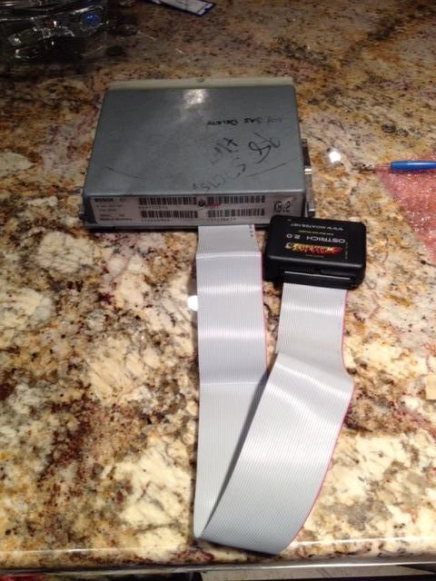
Components you need:
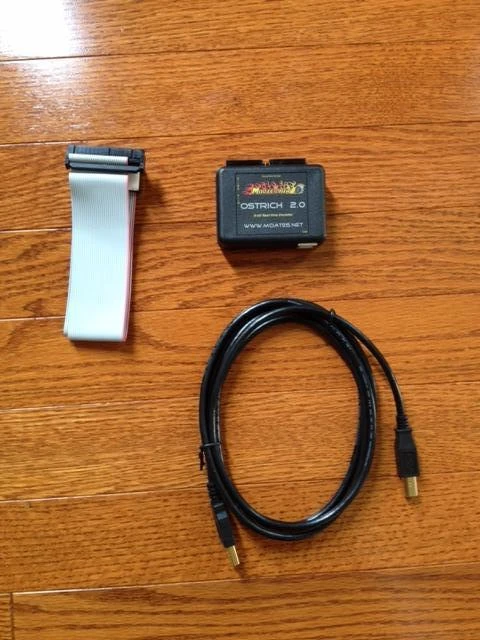
Floppy Cable such as this
Your ECU
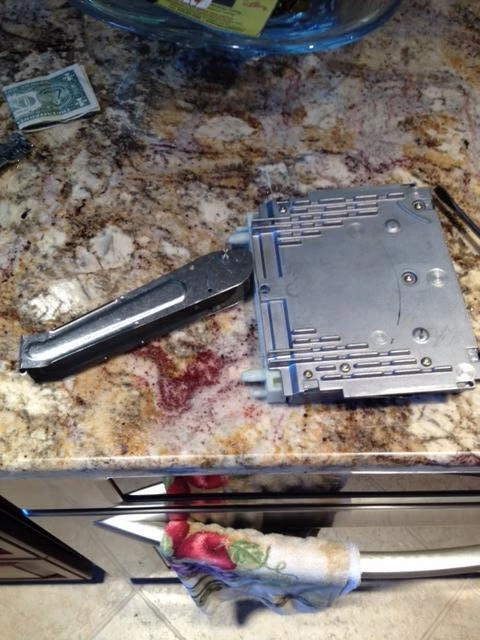
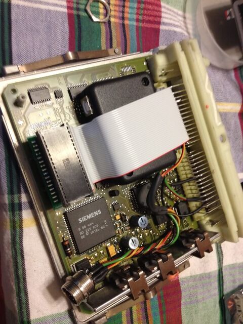
First things first, you're going to open up the ECU:
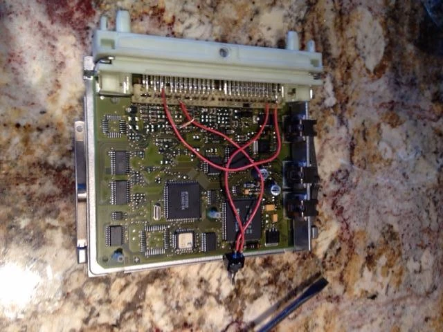
All opened up:
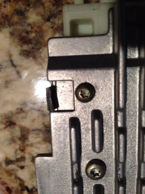
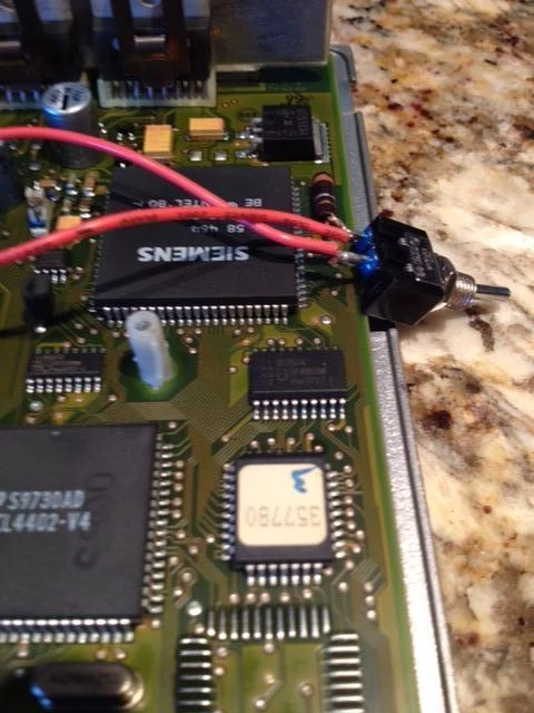
Here is the stock EEPROM Chip (right under the toggle):
Next you'll want to remove the chip, Simply Volvo used a dremel but here is an alternate recommended method:

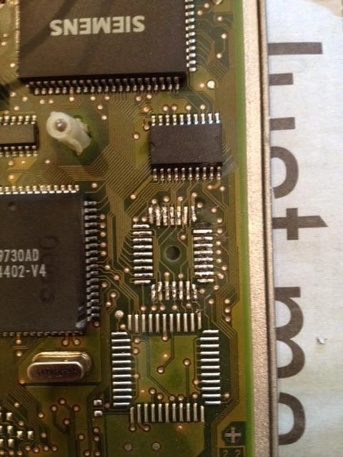
It should look like this once the chip is removed and all cleaned up:
Now for the actual install, you have a couple of options to get it all wired up:
Method 1 (soldering floppy cable to the ECU)
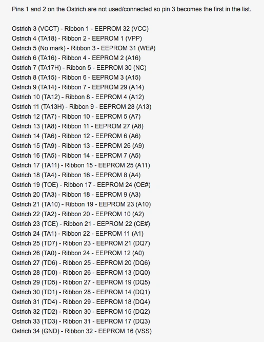
First, here is a pinout of the EEPROM chip pinout:

Here is a pinout of the Ostrich:
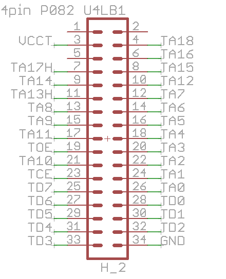
If you look at this picture, you see pin 1, if you are looking directly at the ostrich connector, pin 1 on the schematic is the upper most right pin on the ostrich connector.
So..
Pin 1 = Upper most right
Pin 33 = Upper most Left
pin 2 = Bottom most right
Pin 34 = Bottom most Left
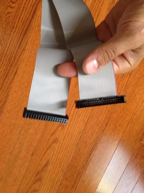
Now for the floppy cable, first cut off the male connector:
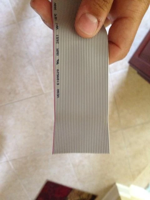
pin 1 is the wire that is pink (or colored). So the pink wire would correlate upper most right on the ostrich connector, but since nothing is connected to that I just snipped it. Pin 2, bottom most right is the second wire on the ribbon cable (next to the pink). That has no connection either so can be cut. The next wire correlates to pin 3, which is VCCT. You can now follow the pattern below to figure out which wires correlate to which pin.
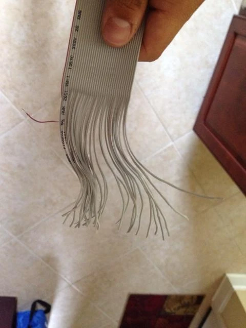
Split the cables:
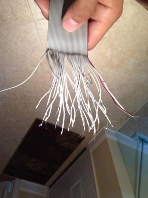
You can go ahead and cut away the wires you don't need:
Now go ahead solder all of the wires to the appropriate pads:
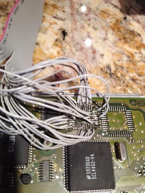
All buttoned up again:
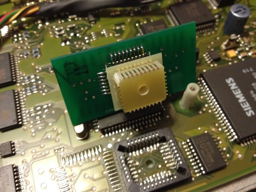
Method 2 (Easier to solder):
For the alternate method, you will also need:
DIP-32 to PLCC-32 IC Adapter(Part E32-0035)
1. Desolder the PLCC32 chip using the above youtube video.
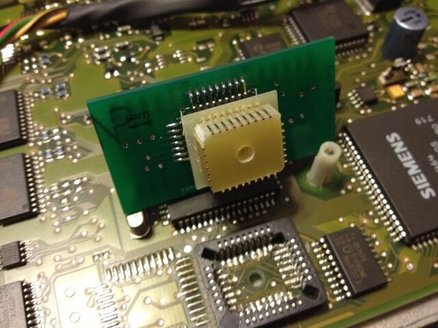
2. Solder in the PLCC32 Socket:
heres another video for hints:

3. Plug the adapter into the socket, then plug the cable into the adapter, then the cable into the ostrich:

Setting Up Ostrich:
- Install FTDI Drivers from here.
- Then, on the ostrich, on the side there are little switches. These need to be set to 28/32 and 32.
- Plug in the ostrich
- Open up tunerpro RT.
- You can then use all of the Emulation features like upload and emulate, etc. Refer to the help manual for this.
Credit to Simply Volvo and Hussein, compiled and reposted.